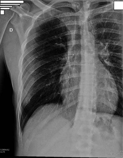
Exposure Factors

70-80
Kilovoltage (kV)
40-65
Milliampere-seconds (mAs)
Large Focus
Focus Type
100 cm
SID (Source-to-Image Distance)
With Bucky
Configuration

Average exposure: Parameters for optimal rib visualization

Visible Anatomical Structures

The following must be clearly observed:

Plate Size and Orientation

35 × 43 cm
Longitudinal

Longitudinal orientation to cover the entire rib cage

Positioning Options

Supine Decubitus

Higher diaphragm → visualization of infradiaphragmatic ribs

Shoulders in the same transverse plane

Upright (Bipedestation)

Lower diaphragm → visualization of supradiaphragmatic ribs

Shoulders in the same transverse plane

Specific Positioning

Patient with back in contact with the wall bucky
Upper limb of the affected side abducted
Center as needed: T6 for upper ribs or T10 for lower ribs
Usually only the ribs of the affected side are included
Both sides can be included if necessary
Cassette centered with the central ray

Central Ray Point

T6
Upper Ribs

For supradiaphragmatic ribs

T10
Lower Ribs

For infradiaphragmatic ribs

Supine decubitus: Vertical ray

Upright: Horizontal ray

SPECIFIC RESPIRATORY INSTRUCTIONS

Upper Ribs

Maximum inspiration before exposure

Hold breath or breathe shallowly during exposure

Lower Ribs

Maximum expiration before exposure

Do not breathe during exposure

Common Technical Challenges

Frequent problems in rib cage projection:

Solution: Clearly identify which ribs need visualization and adjust position, centering, and respiration accordingly

Clinical Considerations

Rib fractures
Pneumothorax
Bone metastases
Thoracic trauma

Technical Variations

Trauma Patient

Use supine decubitus without moving the patient, prioritizing comfort over ideal position.

Geriatric Patient

Possible difficulty abducting the arm, adjust according to available mobility.

Pediatric Patient

Reduce exposure according to age and ALARA protocol, adjust plate size.

``` --- ### 2. Tórax AP Lordosis (Thorax AP Lordotic) ```html Thorax AP Lordotic - Radiological Protocol

Exposure Factors

110-125
Kilovoltage (kV)
3-5
Milliampere-seconds (mAs)
Large Focus
Focus Type
180 cm
SID (Source-to-Image Distance)
With Bucky
Configuration

Note: Use high kilovoltage to reduce contrast and see structures behind the heart and clavicles.

Visible Anatomical Structures

The following should be observed clearly:

Plate Size and Orientation

35 × 43 cm
Portrait or Landscape

Depends on the patient's build.

Patient Positioning

Patient in upright position, separated about 30 cm from the bucky.
Leaning back until the shoulders and back touch the bucky.
Hands on hips with palms facing outward (rotate shoulders forward).
Neck slightly extended to move the chin out of the field.
Maximum inspiration: Full lung expansion.

Central Ray Specifications

Horizontal / Perpendicular

Point of Entry: Mid-sternum (T7 level).

Direction: Straight to the center of the image receptor.

Alternative: If the patient cannot lean, angle the ray 15-20° cephalad.

Acceptable Image Criteria

Symmetry

Sternoclavicular joints equidistant from the spine.

De-projection

Clavicles must be above the lung apices.

Visualization

Clear lung markings in the apices.

Inspiration

Good lung expansion visible.

Technical Variations

Trauma Patient

Perform AP supine with 15-20° cephalad angulation of the ray.

Geriatric Patient

Possible difficulty with lordotic position, consider supine alternative.

Pediatric Patient

Reduce exposure based on age and ALARA protocol, adjust plate size.